Correlogo Help page
Contents:
0. Preface
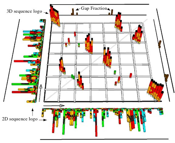
CorreLogo is the name of a web server that helps to detect correlated mutations in RNA and DNA sequence alignments. It generates what we call a "3D sequence logo". This is an extension of the sequence logo concept. A conventional sequence logo (called here a 2D sequence logo) shows the information content and the residue composition of individual columns of a sequence alignment, replacing the concept of a "consensus sequence". A 3D sequence logo consists of a square matrix region that shows columns with high mutual information. The mutual information is a measure of how much the residues in two alignment columns are correlated. Alignment positions that correspond to an RNA base pair tend to favour the nucleotide pairs AU, GC and the wobble base pair GU. This bias in pair composition (instead of uniform frequencies of all 16 base pairs) results in a mutual information value greater than zero. Each colum of the 3D sequence logo consists of a stack of bars that represent by their color-coding the residue composition of a pair of alignment columns. Additionally, a reference secondary structure can be indicated by a set of black cubes floating above the individual stacks.1. Quickstart
For a really quick start, simply click "Submit Query" at the bottom of our example submission form. If you want to run your own set of sequences or you want to customize the output, enter values into the sections one to threer of the empty submission form. Sections 2 and 3 of the submission form contain optional parameters. For more detailed information about the generated 3D sequence logo and the available options, read the corresponding sections in this help text.2. Explanation of the generated 3D output
Figure 1:
|
| The 3D model generated based on information from the provided RNA or DNA alignment is a visualization of several different alignment properties. |
The stacks in the square matrix region (termed "3D sequence logo") indicate pairs of alignment columns with high mutual information. The bars are colored according to the composition of bases of that alignment column. The colors red, orange and yellow indicate complementary base pairs (GC, AU and GU respectively), the colors AA, CC, GG and UU are mapped onto different shades of green, the pairs AG, AC and CU are colored dark medium and light blue respectively. In Figure 2 the color coding for the base pairings is shown.
Figure 2:
3. Description of input parameters
3.1 Sequence alignment in FASTA format (required)
The FASTA format is often used to describe sequence alignments. An example for two hypothetical sequences with the names "Sequence A" and "Sequence B" is:>Sequence A
AUGCCA-AUCCA
>Sequence B
UUGC-ACUU-CA
3.2 Secondary Structures in Bracket Notation
The bracket notation is a compact and effective way to communicate RNA secondary structures. It consists of one word with n charcters. Each character corresponds to one column of the sequence alignment. Possible values are ".", "(" and ")", corresponding to no base pair, 5' partner of base pair, 3' partner of base pair respectively. Instead of the "." character a "-" (dash) character can be used. An example compatible with the sequence alignment given above is:..((...))...
3.3 Color modes
The color mode specifies the coloring used for the bars that indicate the mutual information between two alignment columns. Currently two different color modes are available:1) "Standard"
The colors red, orange and yellow indicate complementary base pairs (GC, AU and GU respectively), the colors AA, CC, GG and UU are mapped onto different shades of green, the pairs AG, AC and CU are colored dark medium and light blue respectively.2) "Rainbow"
This mode colors a bar according to the mutual information of the pair of alignment columns. The colors are ranging from blue (mutual information values close to zero bits) to green (values around 0.8 bits) to red (values around 1.6 bits).3.4 Lower Cutoff Parameter
This value specifies the minimum value of the mutual information (in bits) for a column to be displayed with VRML. This option is useful for controlling the number of polygons that have to be rendered. If you choose a very low value (like 0.0 bits), very many columns are displayed, the resulting VRML file might look cluttered and be slow to handle with a viewer. A too large cutoff will prevent useful information to be part of the plot.Useful range: 0.0 to 1.0 bits. Note: all cutoff parameters (sections 3.4 to 3.6 in this help text) are applied simultaneously.
3.6 Upper Cutoff Parameter
The upper cutoff parameter gives the user an option to make the generated 3D sequence logos less "busy". If for example the user specifies a value of 0.8 bits as an upper cutoff parameter, mutual information stacks corresponding to values greater than 0.8 bits are not drawn. Default is that the upper cutoff is not active. Use this option with care. Note: all cutoff parameters (sections 3.4 to 3.6 in this help text) are applied simultaneously.3.5 Standard Deviation Cutoff Parameter
The standard deviation cutoff parameter specifies the number of standard deviations that the mutual information has to exceed in order be displayed. This option is useful for controlling the number of polygons that have to be rendered. If you choose a very low value (like 0.0), very many columns are displayed, the resulting VRML file might look cluttered and be slow to handle with a viewer. A too large cutoff will prevent useful information to be part of the plot.Useful range: 0.0 to 3.0 standard deviations. Zero or negative values deactivate applying the relative cutoff. Note: all cutoff parameters (sections 3.4 to 3.6 in this help text) are applied simultaneously.
3.7 Error Bars
The presented mutual information values already incorporate a small sample correction. This correction is necessary, because it has been shown that replacing probabilities with frequencies leads to a bias in computed information value. If one takes small samples repeatedly, one can define a mean and a standard deviation of this bias. The error bars that can be generated with the 3D representation correspond to one standard deviation of the error correction. More details about how this error bar is computed can be found in the manuscript describing this server (submitted).3.8 Collapsing of Alignment
With the option "collapse wrt #" it is possible to remove all columns of an alignment that correspond to a gap in the sequence with the chosen number. Possible values are 1 to n with n being the number of sequences in the alignment. The default is to leave this text field empty which indicates that the sequence alignment will not be collapsed.3.9 Reading Frame
The "reading frame" option controls the optional drawing of a set alternating bars that indicate by their 3 different colors (blue, green, red) three possible reading frames. This option is not available then drawing the 2D sequence logo in "flat" mode.4. Help concerning the JavaView Applet
JavaView is a java program for viewing 3D graphics data. More detailed information about JavaView (also in case of trouble-shooting) can be found at the homepage of the authors of the program at http://www.javaview.de. Please see also the references of the JavaView authors below.JavaView is used here as an applet (JavaView-Light). We found that it works very nicely, however your web browser might impose restrictions on the maximum amount of available memory for applets. This can lead to a restriction of the maximum number of polygons that can be viewed effectively. If that is a problem, you might consider using either alignments with shorter sequences, switching of server options that decrease the number of polygons or downloading the stand alone version of JavaView here. The raw JVX output generated by the CorreLogo server can then be used as an input for the stand alone JavaView program.
If, instead of the Javaview 3D graphics output, you obtain a message that contains the phrase "Loading failed" it means that something is seriously malfunctioning on behalf of the CorreLogo server (probably one of our computers is down). In this case, please contact the CorreLogo server administrator.
References:
Publication of Interactive Visualizations with JavaView. Konrad Polthier, Samy Khadem, Eike Preuss and Ulrich Reitebuch in: Multimedia Tools for Communicating Mathematics, Eds: J. Borwein, M. Morales, K. Polthier, J.F. Rodrigues, Springer Verlag (2002). CD with software included.Visualize Mathematics on the Internet. Mirek Majewski and Konrad Polthier in: Proc. of the 9th Asian Technology Conference in Mathematics, (2004), pp. 465-474
Mathematical Visualization and Online Experiments with JavaView. Konrad Polthier in: M. Emmer (Ed) Mathematica e Cultura 3, Springer Verlag (2000), Preprint No. 447 TU-Berlin, SFB 288, 2000
5. Help concerning VRML files
VRML is a format for communicating 3D graphics data. More general information about VRML can be found here.Our server generates VRML 2.0 format. That is important, because some (outdated) viewers expect VRML 1.0. Another source of confusion are the terms VRML 95 and VRML 97. For most practical purposes, one can equate VRML 95 with VRML 1.0 and VRML 97 with VRML 2.0. In this document, we refer to VRML 2.0 (aka VRML 97) as "VRML".
Web browsers are typically not shipped with a default plugin for interpreting VRML data. In other words, if you do not have a VRML plugin installed, you have to download and install a VRML plugin or stand alone binary that is compatible with your web browser and operating system. You can test your installation, by clicking here to obtain a pre-computed 3D model (of tRNA). In the following we provide a non-exhaustive list of VRML viewers that we tested our server with:
Linux:
OrbisnapVrmlview
Windows:
Cortona (plugin)Note: If you installed a VRML viewer as a standalone binary (and not as a plugin), your browser preferences might have to be changed: Add two entries, such that files with the ending ".wrl" as well as documents of the type "x-world/x-vrml" are opened by the VRML viewer binary you installed.
Reference
The following paper is published in the web-server issue of Nucleic Acids Research:
E. Bindewald, T.D. Schneider, B.A. Shapiro:
CorreLogo:
An online server for 3D sequence logos of RNA and DNA alignments
Nucleic Acids Res.
2006 Jul 1;34(Web
Server issue):W405-11. PubMed PMID: 16845037; PubMed Central PMCID: PMC1538790
HTML
Useful Links
Go to:CorreLogo homepage.
CorreLogo server submission form.
CorreLogo server submission form with example sequences.
Top of this page.